| Chrysler Air-Raid Siren Maintenance Manual | |
|
[
BACK ]
[
TOC ] [
NEXT ]
CHRYSLER AIR-RAID SIREN The carrying ability and the efficient operation of
the Chrysler Air-Raid Siren will be affected if care in the selection of
the location and the manner of installation are not given careful
consideration. The following recommendations should be considered: LOCATION: If full coverage is desired, the Sirens should not
be more than 2 miles apart. The highest building in each locality, with a
structural strength sufficient to withstand a weight of approximately
6500 lbs., should be selected. Consideration should be given to the accessibility
of the roof. An inside stairway is preferred although a fire escape may
be used. Any necessary reinforcements that may apply to
the individual structure should be made and, at the same time, making
certain the base or foundation upon which the Siren unit is to be
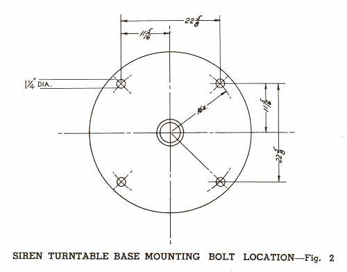
installed, is level. INSTALLATION Installation should be made on a corner of the
structure, or over a supporting wall, and as convenient as possible to
the entry to the roof. The Siren should be installed level, with the base
of the turntable securely bolted to its foundation. See Figure 2 for
location of bolts. Provisions for a 110 volt A. C. electric line
should be made to the Siren installation to be used in connection with
the engine water jacket heater and the battery trickle charger. TO DISASSEMBLE SIREN The engine and blower units are properly aligned on a
rigid frame. Therefore, it is advisable to make installation of the
Siren as a complete unit. In any instance where the Siren must be disassembled
for installation purposes, the following procedure will apply. Remove half-around sheet metal guard between
engine unit and horn unit. Place wooden blocks under each end of frame so it
will not tip when weight of the horn is removed. Remove the two dowel pins, one located on each side
of the horn unit at the flange, (Drive the dowel pins upward.) Remove the two sheet metal panels located just above
the dowel pins. With the use of a hoist, raise the horn blower unit until the
weight is off the frame and then slide it back until the spline shaft
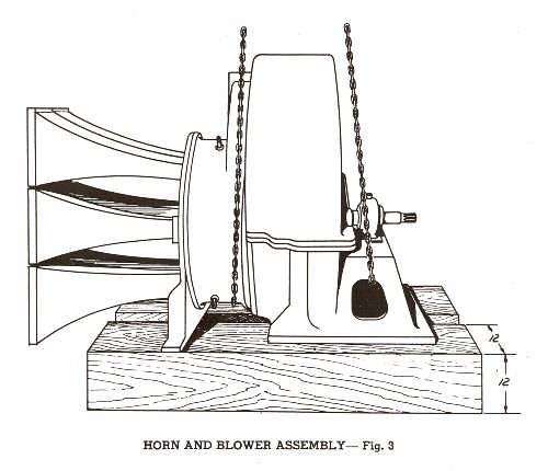
slides out of the universal joint flange. IMPORTANT: FIXTURES ARE ATTACHED TO THE TOP OF THE BLOWER
HOUSING FOR RAISING AND LOWERING THE BLOWER ASSEMBLY. WHEN THESE
FIXTURES ARE NOT CONVENIENT TO USE THE SLING CHAINS OR HOOKS SHOULD BE
ATTACHED AS SHOWN IN Fig. 3. UNDER NO CIRCUMSTANCES SHOULD THE CHAINS BE PLACED
UNDER THE HORNS. IF IT IS NECESSARY TO SET THE HORN BLOWER UNIT ON
THE FLOOR, IT SHOULD REST ON 12"x12" TIMBERS AS INDICATED IN Fig. 3.
DO NOT PERMIT THE UNIT TO REST DIRECTLY UPON THE BLOWER HOUSING OR THE
HORNS. To reassemble the Siren, reverse above operations. |
|