|
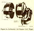
Fig. 6.
Carburetor Air Cleaner
(A.C. Type) |
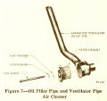
Fig. 7. Oil Filler Pipe and Ventilator Pipe Air Cleaner |
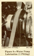
Fig. 8. Water Pump Lubrication
(1 Fitting) |
|
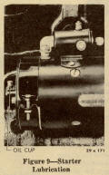
Fig. 9. Starter Lubrication |
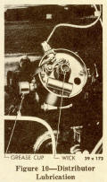
Fig. 10. Distributor Lubrication |
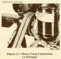
Fig. 11. Water Pump Lubrication
(2 Fittings) |
|
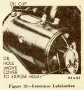
Fig. 12. Generator Lubrication |

Fig. 13. Governor Lubrication |
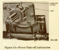
Fig. 14. Power Take-off Lubrication |
|
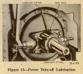
Fig. 15. Power Take-off Lubrication |

Fig. 16. Cross Sectional
View of Engine |
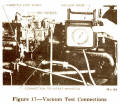
Fig. 17. Vacuum Test Connections |
|

Fig. 18. Cylinder Head
Tightening Sequence |
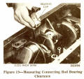
Fig. 19. Measuring Connecting
Rod Bearing Clearance |
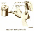
Fig. 20. Fitting Piston Pin |
|
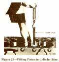
Fig. 21. Fitting Piston in
Cylinder Bore |
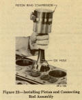
Fig. 22. Installing Piston and Connecting Rod Assembly |

Fig. 23. Valves and Guides |
|
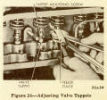
Fig. 24. Adjusting Valve Tappets
|
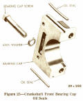
Fig. 25. Crankshaft Front Bearing
Cap Oil Seals |
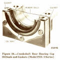
Fig. 26. Crankshaft Rear Bearing Cap Oil Seals and Gaskets
(Model IND. 9 Series) |
|
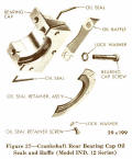
Fig. 27. Crankshaft Rear Bearing Cap Oil Seals and Baffle
(Model IND. 12 Series) |
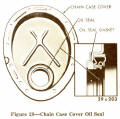
Fig. 28. Chain Case Cover Oil Seal
|
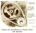
Fig. 29. Installation of
Timing Chain and Sprocket |
|
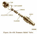
Fig. 30. Oil Pressure Relief Valve |

Fig. 31. Adjustment of
Automatic Choke |

Fig. 32. Governor Adjustments
(Pierce Model A-1557) |
|
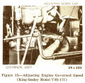
Fig. 33. Adjusting Engine
Governed Speed
(King-Seeley Model V9S-171) |
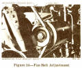
Fig. 34. Fan Belt Adjustment |
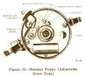
Fig. 35. Breaker Points
(Adjustable Screw Type) |
|
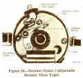
Fig. 36. Breaker Points
(Adjustable Breaker Plate Type) |
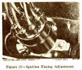
Fig. 37. Ignition Timing Adjustment |

Fig. 38. Wiring Diagram |
|
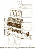
Fig. 39. Cylinder Block, Crankshaft, Pistons, Connecting Rods,
Sprocket, Pulley and Related Parts |

Fig. 40. Cylinder Block, Head, Camshaft, Valves, Tappets, Timing
Chain, Sprocket and Related Parts |

Fig. 41. Cylinder Block, Manifold and Related Parts |
|
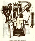
Fig. 42. Engine - Center Section View |

Fig. 43. Oil Pump Disassembled |

Fig. 44. Oil Pressure Relief Valve Disassembled |
|

Fig. 45. Water Pump Disassembled
(Model IND. 9) |
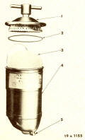
Fig. 46. Oil Filter |

Fig. 47. Water Pump Disassembled
(Model IND. 12) |
|
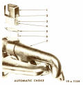
Fig. 48. Automatic Choke |
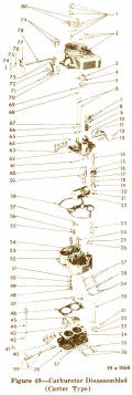
Fig. 49. Carburetor Disassembled
(Carter Type) |
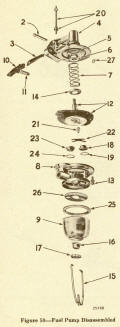
Fig. 50. Fuel Pump
Disassembled |
|
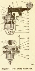
Fig. 51. Fuel Pump Assembled |
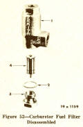
Fig. 52. Carburetor Fuel Filter
Disassembled |

Fig. 53. Governor Throttle Lever, Bearings, Rocker Shaft, Rocker
Yoke and Related Parts |
|
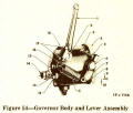
Fig. 54. Governor Body and
Lever Assembly |

Fig. 55. Governor Weight, Pin, Drive Shaft, Bearings and Sleeve |

Fig. 56. Generator Disassembled |
|

Fig. 57. Starter Disassembled
(Overrunning Clutch Type) |
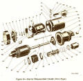
Fig. 58. Starter Disassembled
(Bendix Drive Type) |
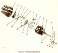
Fig. 59. Distributor Disassembled |
|

Fig. 60. Clutch Disassembled |

Fig. 61. Power Take-off Disassembled
(Ball Bearing Type) |

Antifreeze Table |
